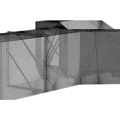
Flue Gas Duct Modeling
CFD modeling is a competitive option for flue gas analysis. Gas mixtures with temperature levels and combustion byproducts that are hazardous to humans pose little threat to health and safety when in numerical form.
Basic level models – steady state providing time averaged results for flow at anticipated gas density and pressure levels.
- Duct layout – Models are typically required for head loss calculations to size induced draft or forced draft fans, locate turning vanes, etc. Areas of potential soot deposition can be documented as well.
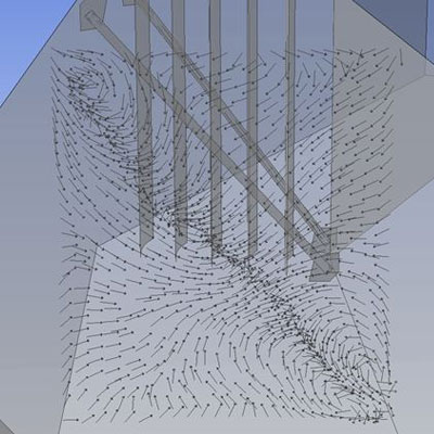
- Inlet flow conditioning – The efficacy of flue gas treatment elements like electrostatic precipitators, heat exchangers or desulfurization units are heavily dependent on the velocity profile of the gas entering the unit. CFD modeling at these locations helps optimize the duct transition geometry for good velocity distribution and minimal head loss.
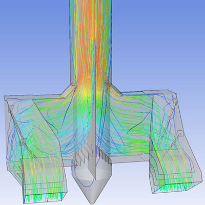
Multi-physics models – In addition to the fluid flow solution, the CFD code can be modeling thermodynamic inputs concurrently. Particle tracking, species tracking and droplet evaporation models are also available and offer excellent utility in design optimization.
- Mercury capture using activated carbon injection – Running a particle trajectory model in conjunction with a flow model records the path taken by each particle. Furthermore, a statistical data base of residence times is created thus allowing for comparison of variables such as alternative lance placement, sorbent particle input rate, or placement of baffles and vanes.
- Electrostatic precipitators – Proper inlet flow conditioning as described above will help maximize precipitator performance. If required, it is possible to run a particle trajectory model wherein the boundary conditions for both the particles and the collection surfaces behave as they would if electrostatically charged.